F4BM220 PTFE RF Circuit Board with Low Dielectric Loss
1.Introduction
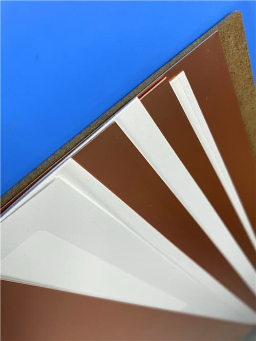
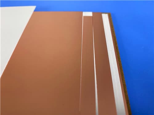
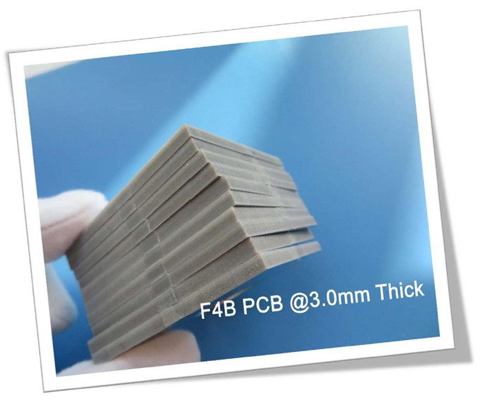
Wangling's F4BM220 is an advanced PTFE-based laminate engineered for high-frequency applications. Composed of fiberglass cloth and PTFE resin, it delivers:
Lower dielectric loss vs standard F4B220
Enhanced stability with controlled Dk (2.2±0.04 @10GHz)
Two copper foil options:
F4BM220: ED copper (general use)
F4BME220: RTF copper (low PIM for precision RF)
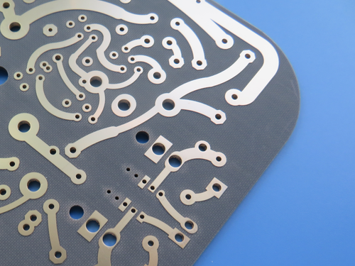
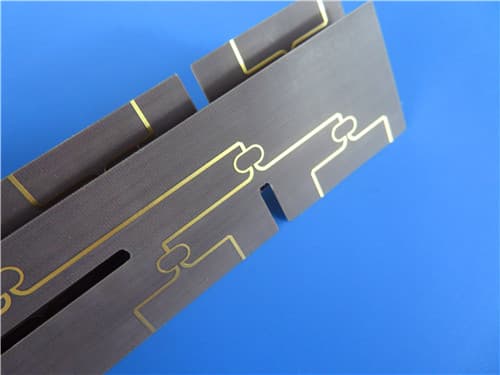
Ideal for phase shifters, power dividers, and satellite communication systems requiring consistent electrical performance.
2.Key Performance Features
Dielectric Constant: 2.2±0.04 @10GHz
Dissipation Factor: 0.001 @10GHz
CTE: 25/34/240 ppm/°C (X/Y/Z)
Thermal Stability: TCDk -142 ppm/°C (-55°C to 150°C)
Moisture Resistance: ≤0.08% absorption
Flame Rating: UL 94V-0
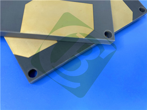
3.PCB Specifications at a Glance
| Specification | Details |
|---|
| Base Material | F4BM220 PTFE Laminate |
| Layer Configuration | Double-sided (2-layer) |
| Board Dimensions | 90mm × 90mm (±0.15mm) |
| Trace/Space | 10/10 mils |
| Minimum Hole Size | 0.7mm |
| Via Type | Through-hole only |
| Board Thickness | 6.1mm |
| Copper Weight | 1oz (outer layers) |
| Via Plating | 20μm |
| Surface Finish | Immersion Gold |
| Silkscreen | None (Top/Bottom) |
| Solder Mask | None (Top/Bottom) |
| Quality Assurance | 100% Electrical Tested |
4.PCB Stackup: 2-layer rigid PCB
Copper_layer_1 - 35 μm
F4BM220 Core - 6.0 mm
Copper_layer_2 - 35 μm
5.PCB Statistics:
Components: 2
Total Pads: 9
Thru Hole Pads: 5
Top SMT Pads: 4
Bottom SMT Pads: 0
Vias: 4
Nets: 2
6.Typical Applications
Phase array antennas
Satellite communication feed networks
RF power dividers/couplers
Radar and microwave systems
7.Quality Assurance
IPC-Class 2 compliant
100% electrical tested
Global availability
Gerber RS-274X support
|
.jpg)
.jpg)